Description
This 100W RF power amplifier is designed for defense and commercial scenarios, supporting wideband RF signal amplification at 2000-7125MHz. In defense fields, it is applicable to tactical communication, radar detection, electronic countermeasures, and defense RF test systems. For commercial use, it covers RF amplification for 5G/6G communication base stations, signal enhancement for satellite ground stations, industrial RF testing equipment, RF R&D and testing in scientific research laboratories, and signal amplification for wireless communication devices. Featuring compact size and light weight, it is suitable for portable field deployment, fixed base station installation, and rack-mounted use in laboratories. It operates stably in a wide temperature range of -20℃ to +60℃, meeting RF amplification requirements in harsh environments.
Specification
Typical performance at 28V DC +25oC, and in a 50Ω system.
RF / ELECTRICAL | ||||
PARAMETER | MIN | TYP. | MAX | UNIT |
Operating Frequency | 2000 | 7125 | MHz | |
RF INPUT | 0 | dBm | ||
Power Gain@ Pin=0dbm | 50 | dB | ||
P-sat Output Power@ Pin=0dbm | 50 | dBm | ||
Power Gain Flatness@ Pin=0dbm | ±2.5 | dB | ||
In/Out Impedance | 50 | Ω | ||
Spurious Signals | -60 | dBc | ||
Harmonic Signals | -20 | –10 | dBc | |
Input VSWR | 1.75 | –– | ||
Operating Voltage | 28 | V | ||
Currents@100W | 19 | 22 | A | |
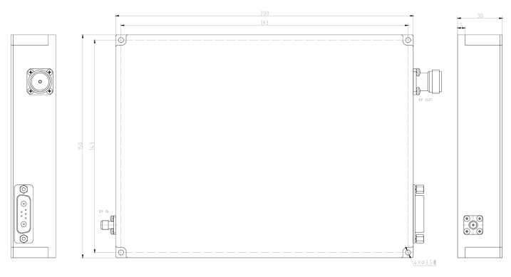
MECHANICAL | ||
PARAMETER | VALUE | UNIT |
Dimensions (W x D x H) | 200× 150 × 30 | mm |
RF Connectors (Input / Output) | SMA-KFD / N-KFD | — |
DC & Control Connector | D-SUB 7W2 M | — |
Cooling | External Heatsink Required | — |
Weight | ≤3 | kg |
ENVIRONMENTAL / PROTECTIONS | |||
PARAMETER | MIN | MAX | UNIT |
Operating Temp. | -20 | +60 | °C |
Storage Temp. | -40 | +80 | °C |
Amplifier Safeguard Temp. | +70 | °C | |
Protections | Over temperature protection, over voltage protection (OVP), over current protection (OCP) | –– | |
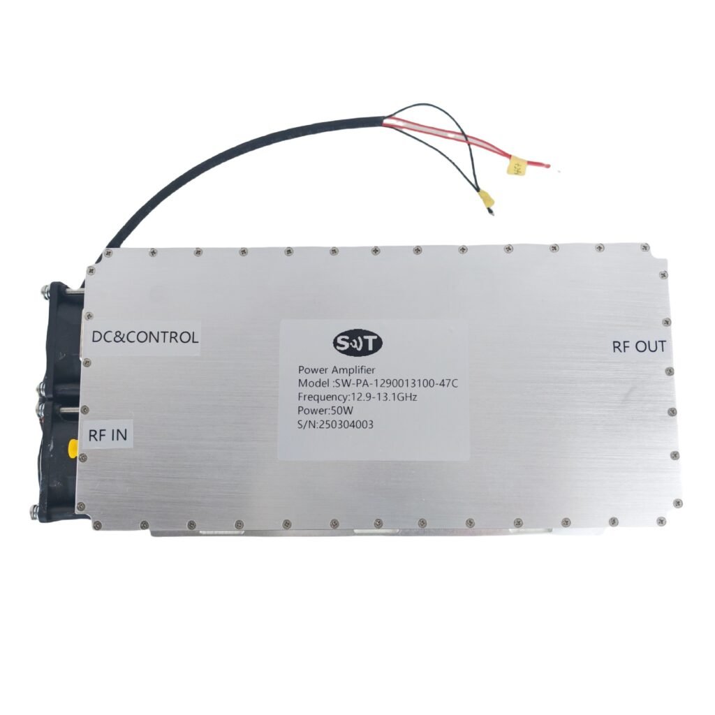
INPUT/OUTPUT panel Connector | |||
AMPLIFIER CONNECTOR TYPE: | —— | ||
TRIAD CABLE PART NUMBER: | —— | ||
NUMBER | interface type | DESCRIPTION | |
X1 | SMA-FK | RF IN | |
X2 | N-FK | RF OUT | |
X3 | D-SUB 7W2 M | DC & Control interface | |
Connector Definition | ||
AMPLIFIER CONNECTOR TYPE: | D-SUB 7W2 M | |
TRIAD CABLE PART NUMBER: | —— | |
NUMBER | Definition | DESCRIPTION |
A1 | VDD | +28V |
A2 | GND | GND |
1 | PA Enable | TTL Hi= Enable, TTL Lo = Disable or No Connection |
2 | GND | GND |
3-5 | NC | NC |
Outline Dimensional Drawing (TBD)