Description
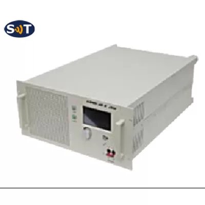
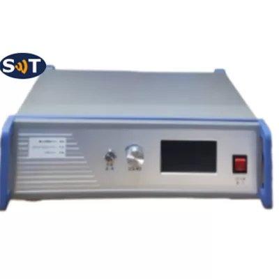
The chassis is designed for both Industrial and commercial applications. The latest device technologies and design methods are employed to offer high power density, efficiency, and linearity in a small, lightweight package.
Specification
Typical performance at 220V AC +25oC, and in a 50Ω system.
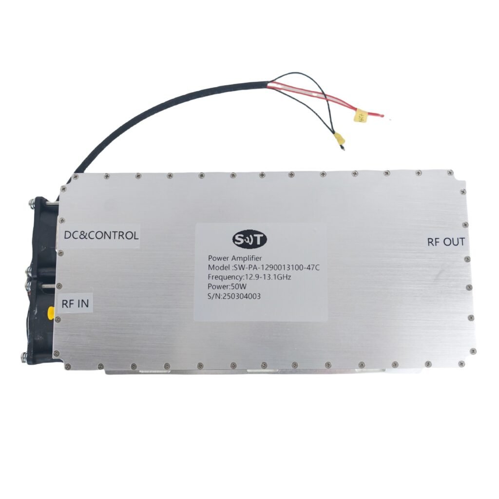
RF/Electrical
| RF/ELECTRICAL | MIN | TYP. | MAX | UNIT | |
|---|---|---|---|---|---|
| Operating Frequency | 1000 | 6000 | MHz | ||
| RF Input | 0 | 5 | dBm | ||
| Power Gain | 50 | dB | |||
| P-1dB Output Power | 50 | W | |||
| P-sat Output Power | 100 | W | |||
| Power Gain Flatness | ±4 | dB | |||
| In/Out Impedance | 50 | Ω | |||
| Spurious Signals | -65 | dBc | |||
| Harmonic Signals | -15 | dBc | |||
| Gain Adjust Range | 31.5 | dB | |||
| Gain Adjust Step | 0.5 | dB | |||
| Operating Voltage | 200 | 220 | 240 | V AC | |
| Supply Power | 1600 | W | |||
| Input VSWR | 2 | ||||
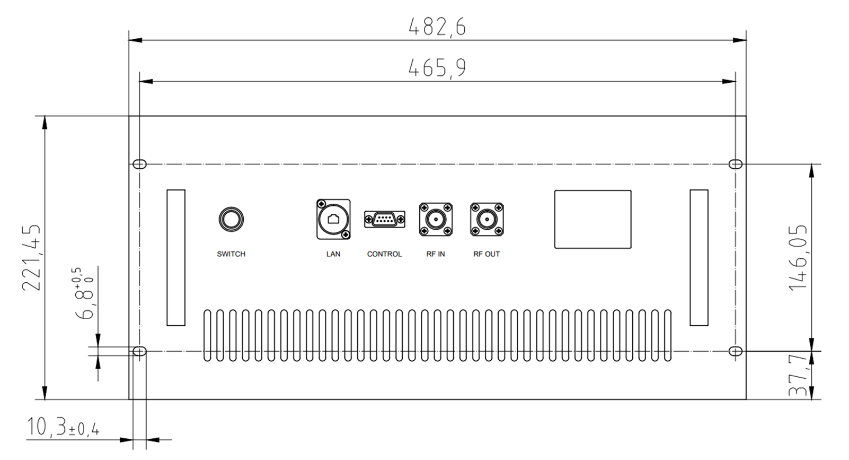
Mechanical
| MECHANICAL | VALUE | UNIT |
|---|---|---|
| Dimensions (W×D×H) | 482×600×223 (19-inch 5U) | mm |
| RF Connectors (Input/Output) | N-K / N-K (N female) | — |
| Control Connector (Option1) | DB9: Power/Gain control + Monitoring | — |
| Control Connector (Option2) | RJ45: LAN remote control | — |
| Cooling | Forced air cooling | — |
| Weight | ≤40 | kg |
| AC Connector | Three-in-one air switch | — |
Environmental/Protections
| ENVIRONMENTAL/PROTECTIONS | MIN | MAX | UNIT |
|---|---|---|---|
| Operating Temp. | -25 | +55 | °C |
| Humidity Range | 0 | 90% | % |
| Amplifier Safeguard Temp. | +80 | °C | |
| Protections | Over-temperature, Input over-power, Over-voltage, Over-current, Output mismatch | ||
Connector Definitions
| NUMBER | INTERFACE TYPE | DESCRIPTION |
|---|---|---|
| X1 | N-FK | RF IN |
| X2 | N-FK | RF OUT |
| X3 | LCD display | Human-computer interface |
| X4 | Three-in-one air switch | AC/220V/50Hz |
| X5 | RJ45 | LAN |
| X6 | DB9 | Control interface |
| X7 | N-FK | Forward coupling port |
| X8 | N-FK | Reverse coupling port |
DB9 Pinout
| PIN NUMBER | DEFINITION | DESCRIPTION |
|---|---|---|
| 1 | PA Enable | TTL Hi=Enable, Lo=Disable |
| 2 | Output Power monitoring | TTL Hi=Normal, Lo=Fault |
| 3 | Temp monitoring | TTL Hi=Normal, Lo=Fault |
| 4 | Voltage monitoring | TTL Hi=Normal, Lo=Fault |
| 5 | Current monitoring | TTL Hi=Normal, Lo=Fault |
| 6 | RXD | RS232 for gain adjustment |
| 7 | TXD | RS232 data transmit |
| 8 | GND | Ground |
| 9 | NC | No connection |