Description
The module is designed for commercial applications. The latest device technologies and design methods are employed to offer high power density, efficiency, and linearity in a small, lightweight package.
Specification
Typical performance at +48V DC +25oC, and in a 50Ω system.
RF / ELECTRICAL | ||||
PARAMETER | MIN | TYP. | MAX | UNIT |
Operating Frequency | 1100 | 1400 | MHz | |
RF Pulsed signal (With External modulation signal) | ||||
RF INPUT | 0 | dBm | ||
Duty cycle | 10 | % | ||
Pulse width | 20 | us | ||
P-sat Output Power | 57 | dBm | ||
Power Gain | 57 | dB | ||
Power Gain Flatness | 2 | dB | ||
Spurious Signals | -55 | dBc | ||
Harmonic Signals | -20 | dBc | ||
Pulse delay(PA ON/OFF time) | 1 | us | ||
Input VSWR | 2 | — | ||
In-Out impedance | 50 | Ω | ||
Operating Voltage | 48 | 50 | V DC | |
Average Current@ 10% cycle | 3 | 4 | A | |
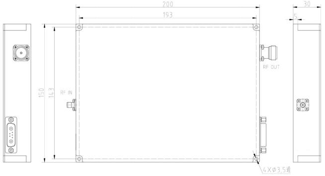
MECHANICAL | ||
PARAMETER | VALUE | UNIT |
Dimensions (L x W x H) | 200x150x30 | mm |
RF Connectors (Input / Output) | SMA- KFD/ N- KFD | — |
DC / Control Connector | D-SUB 7W2 | — |
Cooling | Consider heat dissipation with the system | — |
Mounting | φ3.5-4 Thru Hole | — |
Weight | ≤2 | kg |
ENVIRONMENTAL / PROTECTIONS | |||
PARAMETER | MIN | MAX | UNIT |
Operating Temp. (Housing Temp.) | -20 | +60 | °C |
Humidity Range | 0-95 | % | |
Connector Definition | ||
AMPLIFIER CONNECTOR TYPE: | D-SUB 7W2 | |
TRIAD CABLE PART NUMBER: | —— | |
NUMBER | Definition | DESCRIPTION |
A1 | VDD | +48V |
A2 | GND | GND |
1 | Amp Enable | Enable : TTL “Low”, Disable : TTL “High” (Low : 0~0.5V, High : 2.5~5V) (Pulse modulation synchronous signal, switch time less than 1us) |
2 | GND | Ground |
3 | Output Power monitoring | Output Power Detection (Output pulsed wave analog voltage) @The peak of the pulse wave is relative to RF power (0.1 ~ 3.0V relative to +30 dBm ~ +57dBm) |
4 | Reverse Power monitoring | Reverse Power Detection (Output pulsed wave analog voltage) @The peak of the pulse wave is relative to RF power (0.1 ~ 3.0V relative to +30 dBm ~ +57dBm) |
5 | Temp monitoring | Analog voltage relative to module temperature @10mv/℃:V=0.5+10mv*△℃) (0 .75V relative to 25℃) |