Description
The module is designed for both military and commercial applications. The latest device technologies and design methods are employed to offer high power density, efficiency, and linearity in a small, lightweight package.
Specification
Typical performance at +28 VDC +25oC, and in a 50Ω system.
RF / ELECTRICAL | ||||
PARAMETER | MIN | TYP. | MAX | UNIT |
Operating Frequency | 8000 | 12000 | MHz | |
Operation Mode | CW & Pulsed | |||
Input Pulse Width Range | 50 ns to CW | |||
Input PRF Range | 200 | 350000 | Hz | |
RF INPUT | -5 | 0 | 5 | dBm |
Saturated Output Power At RFO1 | 50 | dBm | ||
Output Power At RFO2 | 20 | dBm | ||
Output Power Step At RFO2 | 1 | dB | ||
Power Gain At RFO2 | 50 | dB | ||
Flatness @ Psat | ±1 | dB | ||
Gain Flatness At RFO1(Over temperature & Frequency) | 5 | dB | ||
Spurious Signals @ Max. Power | -60 | dBc | ||
Harmonic Signals @ Max. Power | -20 | dBc | ||
RFO1 and RFO2 Isolation | 50 | dB | ||
RF Delay (input to RFO1) | 20 | ns | ||
SPDT Switching Time (switching between RFO1 & RFO2) | ˂ 1μs (50% CTL to 10/90% RF) | — | ||
Gain Adjustment | 31dB , 1dB Step, Speed <1 μs | — | ||
Digital Attenuator control signal | TTL (5bits), Parallel | — | ||
Input VSWR | 2 | 2.2 | ||
Output VSWR | 1.8 | |||
Operating Voltage | 18 | 28 | 36 | V DC |
Currents | 15 | A | ||
In-Out impedance | 50 | Ω | ||
Power Supply On/Off Timing | 3 | μs | ||
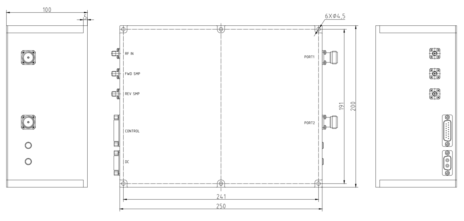
MECHANICAL | ||
PARAMETER | VALUE | UNIT |
Dimensions (L x W x H) | 250*200*100 | mm |
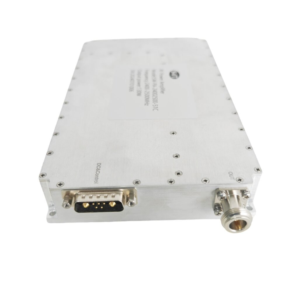
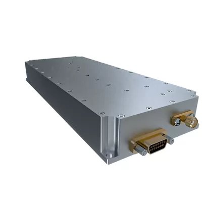
RF Connectors (Input / Output) | SMA- KFD/ N- KFD | — |
DC / Control Connector | D-SUB 2W2 M / D-B15 M | — |
Cooling | Consider heat dissipation with the system(TBD) | — |
Mounting | φ3.5-8 Thru Hole | — |
Weight | ≤8 | kg |
ENVIRONMENTAL / PROTECTIONS | |||
PARAMETER | MIN | MAX | UNIT |
Operating Temp. (Housing Temp.) | –40 | +71 | °C |
Humidity Range | 0-100 | % | |
LED Monitoring | PA module must be have a LED for DC power on and another LED for RF power monitoring | — | |
Protections | Open/Short Output Protection | — | |
Low voltage protection | — | ||
Reverse Polarity Protection | — | ||
Over Temperature Protection | — | ||
INPUT/OUTPUT PINS | |||
AMPLIFIER CONNECTOR TYPE: | D-SUB 2W2 M | ||
TRIAD CABLE PART NUMBER: | —— | ||
PIN NUMBER | LABEL | DESCRIPTION | |
A1 | +VDC | +28V | |
A2 | GND | Ground | |
INPUT/OUTPUT PINS | ||
AMPLIFIER CONNECTOR TYPE: | D-B15 M | |
TRIAD CABLE PART NUMBER: | —— | |
PIN NUMBER | LABEL | DESCRIPTION |
1 | PA modulation | PA modulation |
2 | GND | Ground |
3 | Port 1 /2 SW Control | Disable: TTL “Low”, Enable : TTL “High” (Low : 0~0.5V, High : 2.5~5V) |
4 | GND | Ground |
5 | Power On/OFF Control | Power On: TTL “High”, OFF : TTL “Low” (Low : 0~0.5V, High : 2.5~5V) |
6 | GND | Ground |
7 | ATT CONTROL1 | Gain Adjustment :TTL (5bits), Parallel 31dB , 1dB Step, Speed <1 μs |
8 | ATT CONTROL2 | |
9 | ATT CONTROL3 | |
10 | ATT CONTROL4 | |
11 | ATT CONTROL5 | |
12-15 | NC | NC |