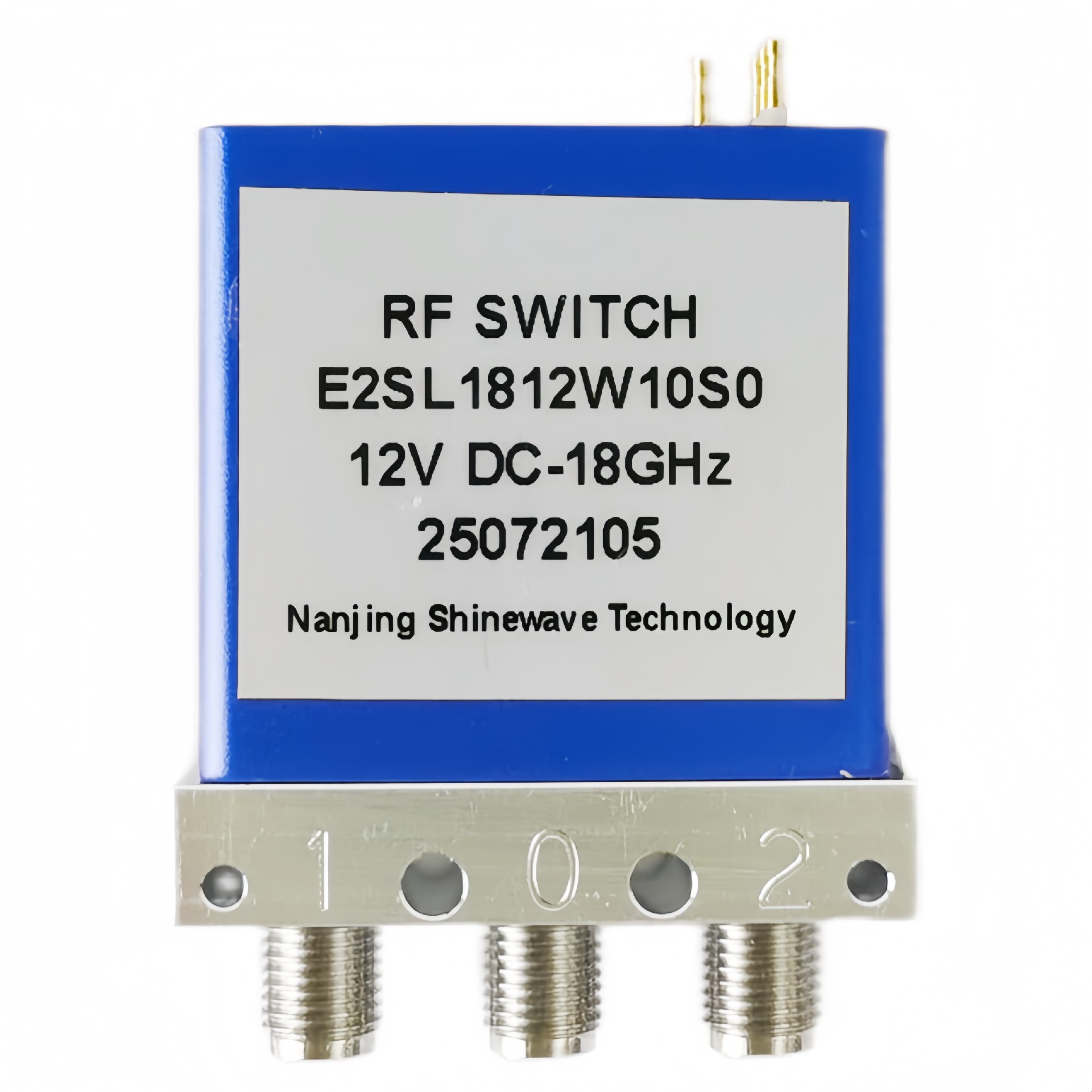
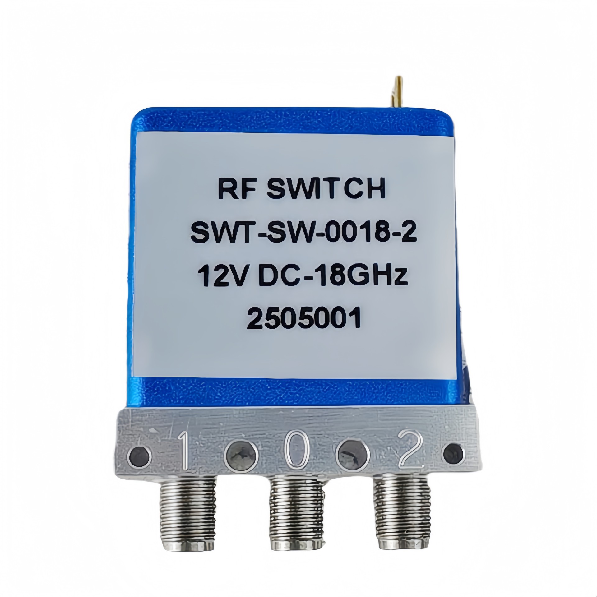
Product Functions
DC to 18GHz
Low loss, Low VSWR, High Isolation ![]() SMA Connector
SMA Connector
Selectable TTL driver control
RF Characteristics
Frequency (GHz) | Ins.loss (dB) | Isolation (dB) | VSWR | RF Power CW (W) |
DC-6 | 0.2 | 70 | 1.2 | 80 |
6-12 | 0.3 | 70 | 1.3 | 60 |
12-18 | 0.4 | 60 | 1.4 | 50 |
Operating Voltage/Coil Current
Operating Voltage(V) | 12 | 24 | 28 | |
Coil Current (mA) | Failsafe | 195 | 100 | 95 |
Latching | 230 | 140 | 120 | |
*It can be selected according to user requirements
TTL | TTL Low(V) | TTL High | |
0-0.3 | 3~5V | 20mA | |
Indicators | Withstand VoltageV (max) | CurrentcapacitymA(max) | Resistance Ω (max) |
50 | 100 | 15 |
* Connect VDC &GND before the function operates
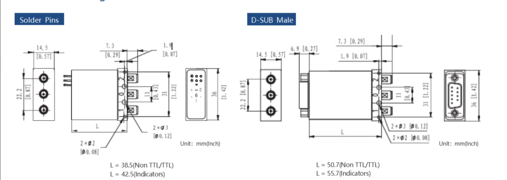
Outline Drawing
Truth Table
Failsafe Non TTL | |||
Actuator Terminals | RF Connector | ||
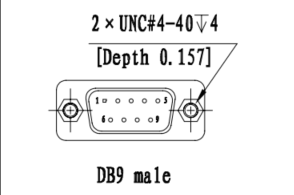
Solder Pins/D-SUB 9Pin Male | |||
Pin No. | Define | No Power,RF 1-0 | |
1 | V | RF 2-0 | |
2 | N/A | – | |
3 | GND | – | |
4 | Ind.1 |
Indicators | RF 1-0 |
5 | Ind.2 | RF 2-0 | |
6 | Ind.com | – | |
7 | VDC | – | |
8~9 | N/A | – | |
Failsafe TTL | |||
Actuator Terminals | RF Connector | ||
Solder Pins/D-SUB 9Pin Male | |||
Pin No. | Define | No Power,RF 1-0 | |
1 | VDC | RF 2-0 | |
2 | TTL | – | |
3 | GND | – | |
4 | Ind.1 |
Indicators | RF 1-0 |
5 | Ind.2 | RF 2-0 | |
6 | Ind.com | – | |
7~9 | N/A | – | |
Latching Non TTL | |||
Actuator Terminals | RF Connector | ||
Solder Pins/D-SUB 9Pin Male | |||
Pin No. | Define | – | |
1 | V1 | RF 1-0 | |
2 | V2 | RF 2-0 | |
3 | GND | – | |
4 | Ind.1 |
Indicators | RF 1-0 |
5 | Ind.2 | RF 2-0 | |
6 | Ind.com | – | |
7 | VDC | – | |
8~9 | N/A | – | |
Latching TTL | |||
Actuator Terminals | RF Connector | ||
Solder Pins/D-SUB 9Pin Male | |||
Pin No. | Define | – | |
1 | VDC | ||
2 | TTL | RF 1-0 | |
3 | GND | – | |
4 | TTL | RF 2-0 | |
5 | Ind.1 | Indicators | RF 1-0 |
6 | Ind.2 | RF 2-0 | |
7 | Ind.com | – | |
8~9 | N/A | – | |
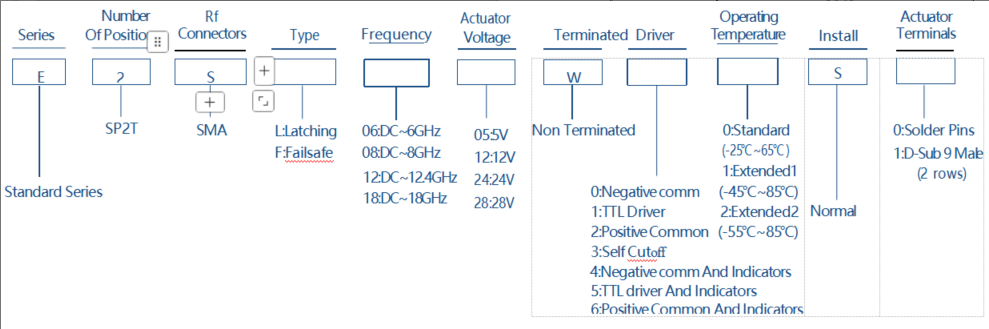
Product Selection