Customized 20~520MHz 100W 50dB RF Module Microwave Power Amplifier for radar, Communication
Description
The RF (Radio Frequency) Power Amplifier is an electronic device used to enhance the power of RF signals. It is primarily used in wireless communication, radar systems, satellite communication, broadcast television, medical equipment, and other fields. The amplifier can amplify low-power RF signals to sufficient levels to ensure signal integrity and prevent excessive attenuation during transmission.
RF power amplifiers typically use high-frequency electronic components such as transistors, power transistors (such as GaN, LDMOS, etc.), integrated circuits, etc., to amplify signals by increasing voltage or current. They have a wide operating frequency range, typically covering frequency bands from tens of kilohertz to several gigahertz, suitable for processing various RF signals.
In applications, RF power amplifiers play a crucial role in wireless communication systems, enhancing signal transmission distance, coverage range, and anti-interference capability. They also have significant applications in radar systems, broadcast television, satellite communication, and medical equipment.
Overall, RF power amplifiers are an indispensable component in modern wireless communication and electronic devices, providing reliable signal amplification solutions for various RF applications.
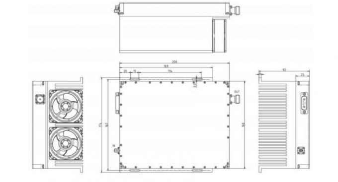
Outline Dimensional Drawing
Specification
| RF / ELECTRICAL | ||||
| PARAMETER | MIN | TYP. | MAX | UNIT |
| Operating Frequency | 20 | 520 | MHz | |
| RF INPUT | 0 | 5 | dBm | |
| Power Gain | 50 | dB | ||
| P-sat Output Power | 50 | dBm | ||
| Power Gain Flatness | ±2.5 | ±3 | dB | |
| Gain Control range | 1 | 30 | dB | |
| In/Out Impedance | 50 | Ω | ||
| Spurious Signals | -55 | dBc | ||
| Harmonic Signals | – 15 | – 10 | dBc | |
| Operating Voltage | 28 | 36 | V | |
| Currents | 14 | A | ||
| Input VSWR | 2 | |||
| MECHANICAL | ||
| PARAMETER | VALUE | UNIT |
| Dimensions (W x D x H) | 200* 160* 25 | mm |
| RF Connectors (Input / Output) | SMA- KFD/ N-Type Female | — |
| DC / Control Connector | D-SUB 7W2 | — |
| Cooling | Air cooled heat dissipation, size to be determined | — |
| Mounting | 3-4 Thru Hole | |
| Weight | ≤4 | kg |
| ENVIRONMENTAL / PROTECTIONS | |||
| PARAMETER | MIN | MAX | UNIT |
| Operating Temp. | -25 | +55 | °C |
| Humidity Range | 0-90 | % | |
| Amplifier Safeguard Temp. | +80 | °C | |
| INPUT/OUTPUT PINS | ||
| AMPLIFIER CONNECTOR TYPE: | D-SUB 7W2 | |
| TRIAD CABLE PART NUMBER: | —— | |
| PIN NUMBER | LABEL | DESCRIPTION |
| 1-2 | +VDC | +28V |
| 3 | GND | Ground |
| 4 | Temp Monitor | Reference voltage : 750mV @ 25°C, Scale : 10mV/°C |
| 5 | Amp Enable | TTL Lo or No Connection = Disable, TTL Hi = Enable |
| 6 | ||
| 7 | GND | Ground |