1 summary
This document specifies the product specifications for the SWT-AJU-X200 sixteen-element navigation anti-jamming all-in-one device (hereinafter referred to as the 'anti-jamming all-in-one device').
The anti-jamming all-in-one system consists of an array antenna, anti-jamming processing module, built-in receiver, and supporting cables. It supports 16-channel signal reception, amplification, down-conversion, filtering, anti-jamming processing, and up-conversion output for BDS_B1, GPS L1, and Galileo E1 frequency signals. The built-in receiver provides PVT (Position, Velocity, Time) calculation output. Powered by 9V-36V DC, it features 1-15-directional interference suppression capabilities including broadband, narrowband, pulse, and sweep frequency jamming.
2 product formation
The product consists of an anti-interference all-in-one machine, test cables, and accompanying documentation, with the components listed below:
Table 2-1 Product Completeness (Single Product Set)
order number | product name | quantity | remarks |
1 | anti-jamming all-in-one machine | 1 | 200mm×200mm |
2 | debug cable | 1 root | J30J-15ZKP debugging line |
3 | Install screws | Group 1 | Group 1: 4 M2.5×2.4 installation screws |
Ø Anti-jamming all-in-one machine product drawing
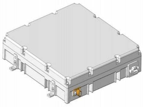
Figure 2-1: Integrated Anti-jamming Device Product Diagram
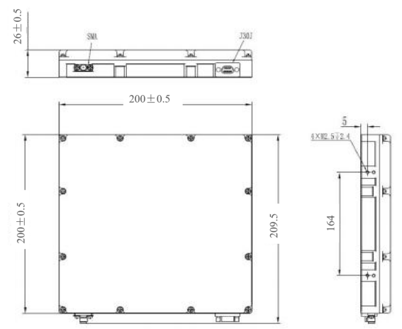
Figure 2-2: Dimensions of the Integrated Anti-jamming Device
Ø debugging cable product drawing
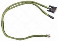
Figure 2-3 Debugging Cable Diagram
1 Product specifications
3.1 major function
1 ) Supports receiving signals from BDS_B1, GPS L1, and Galileo E1 frequency bands.
2 ) It has the ability to suppress various types of interference, including broadband, narrowband, sweep frequency, and pulse interference, in the B1, L1, and E1 frequency bands, as well as the capability to resist combinations of these interferences.
3 ) Supports both soft direct-through and anti-interference modes, allowing users to flexibly switch between them via the serial port.
4 ) The built-in receiver can output the positioning solution after anti-interference processing.
3.2 the key technical indexes
1) frequency immunity
(1)Channel count: 16 channels, supporting BDS_B1, GPS L1, and Galileo E1 bands.
(2)Anti-jamming capability: Capable of suppressing various interference types including broadband, sweep, and pulse in the B1/L1/E1 frequency bands, with resistance to combinations of these interference types.
(3)The number of anti-interference is 1~15 different direction interference sources;
(4)Anti-multipath interference capability: dry signal-to-noise ratio (DSNR) ≥110dB@-130dBm.
(5)Anti-three-band jamming capability: dry signal-to-noise ratio (DSNR) ≥95dB@-130dBm.
(6)Anti-5G wideband jamming capability: dry signal-to-noise ratio (DSNR) ≥80dB@-130dBm.
(7)Anti-jamming range: azimuth 0°~360°, pitch-10°~90°.
Note: The pitch angle is defined as the angle between the space vector of the anti-jamming source and the anti-jamming integrated unit and the horizontal plane, with the y-axis of the aircraft system serving as the pitch axis, where counterclockwise direction is marked as '+' and clockwise direction as '-'.
2) radio frequency output
(1)The output power of radio frequency is-55dBm~-70dBm.
(2)RF impedance: 50 ohms;
(3)Output standing wave: ≤2.0.
3) Built-in receiver metrics
The built-in receiver supports signal reception and calculation at B1, L1, and E1 frequencies, and outputs positioning results through the data interface.
(1)Positioning accuracy: horizontal error ≤7m, vertical error ≤9m (95% confidence, PDOP ≤4).
(2)Speed measurement accuracy: ≤0.2 m/s (95% confidence interval).
4) The surface fire resistance of the antenna port is ≥10W.
5) Operating voltage range: DC9V to 36V.
6) Average power consumption: ≤30W.
3.3 peripheral interface
The antenna has two external interfaces:
1) One J30J power data interface for power supply and data debugging, featuring a J30J-15ZKP connector with 15 pins. The signal definitions are as follows.